You can find any tool by the Menu Structure HERE: https://turbocaddoc.atlassian.net/wiki/display/TC21UG/Menu+Structure
You can find the menu location of any tool by name HERE: https://turbocaddoc.atlassian.net/wiki/display/TC21UG/Tools+Mapped+to+Menus
AEC Dimension Styles
The Style Manager can be used to set various styles for wall dimensions. These dimensions are created with the Wall Dimension tool.
Note: If you want to save styles to a template, see Saving as Templates.
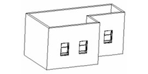
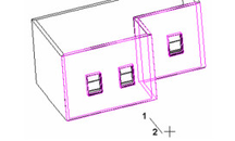
- Start with some walls, and add openings like windows or doors.
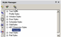
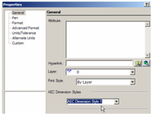
In the Style Manager, there is one style, "Standard," listed under "AEC Dimension styles." This style has one chain, and a preview showing a layout of AEC Dimension styles is below.
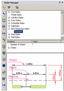
Note: In the Preview area, you can click to zoom part of the graphic. Double-click to fit the graphic in the window. - Activate Wall Dimension, and select one chain of walls, using the Shift key for multiple selection. Select Finish Selection.
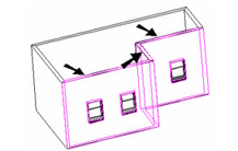
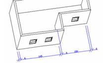
- The next click defines the location of the dimension baseline. The subsequent click defines the dimension angle - if you want the dimensions to proceed along the wall chain, the angle should be perpendicular to the walls.
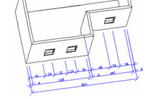
Tip: To ensure a vertical or horizontal angle line, you can use the X or Y lock in the Coordinate Field. - This is the resulting dimension chain in the current style.
Note: If you want to change the properties of the dimensions themselves, such as font or leader lines, see Dimension Properties. - You can change the "Standard" style, but if you want to preserve this style, make sure "Standard" is highlighted, then click Create New Style.
- Assign a name or accept the default.
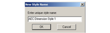
This creates a new style which is a copy of "Standard." - To change the current wall dimension to the new style, open its Properties to the General page.
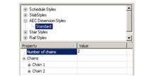
- With the new style highlighted, change the Number of chains to 2.
Note: If Delay Style Modification is enabled, you can see the old and new values for each field. Then you can update the style by clicking Apply Style Changes. If there is no delay, then all changes are implemented immediately. - To separate Chain 2 from Chain 1, add an Offset.
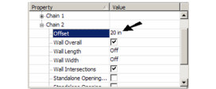
Chain 1 is offset from the baseline, which is where you first clicked to define the dimension line's location. Chain 2's offset is its distance from Chain 1.
- Open the properties for Chain 1 and make these changes.
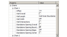
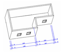
Now Chain 1 dimensions the openings. Chain 2 is still the same as the "Standard" style.
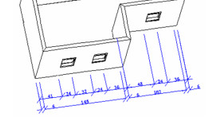
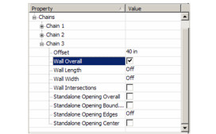
- To add an overall dimension, add Chain 3 and offset it from Chain 2. Only Wall Overall should be checked.
This is the result.