Anchor
One advantage to profile objects is that you can change them by simply editing the profile (or profiles) on which they are based. See Profile Editing.
...
Available in TurboCAD Pro and Platinum only
A compound profile is an open or closed chain of connected curves or lines, or any set of closed curves or closed polylines. You can use compound profiles when you do not want to create a polyline, or convert a chain into a polyline. Compound profiles can be used as paths for sweeps etc., and as profiles that are swept along paths.
You can use blocks as compound profiles, however there are restrictions. You can only only use one element in a block as a path for any given operation. Also, only closed sequences of curves, lines etc. (chains) or closed objects can be used to sweep, revolve etc. All such closed objects in the block selected to sweep, revolve, etc will used in the resulting 3D object.
...
| Table of Contents |
|---|
Prism
...

Creates a 3D object between two 2D objects that lie on different planes. The planes do not have to be parallel.
Both profile objects must be the same type and must have the same number of vertices. For example, you can create a prism between two circles or two rectangles, but not between a circle and a rectangle. Splines and Bezier curves must have the same number of control points.
(If you want to use more than two profiles, or profiles of different type, see Profile Objects Rn3D45129.)
...
Note: A prism is considered to be a Lofting object, and its Properties contain a Lofting Shape page. For details, see Profile Objects Rn3D19033.
...
- If you want to select only simple (single-object) curves, make sure Use Compound Profile is not selected. If you want to use compound profiles, see Profile Objects Rn3D77381.

- Select the two 2D objects.

Polyline to polyline

Spline to spline
You do not have to select closed 2D objects. If you use open objects, a 3D surface will result.

Anchor Rn3D77381 Rn3D77381 Anchor Rn3DCompoundprofilesPrismT Rn3DCompoundprofilesPrismT
PriAnchor Rn3D77381T Rn3D77381T
sm with Compound ProfilesAnchor Rn3DCompoundprofilesPrism Rn3DCompoundprofilesPrism Anchor Rn3D77381P Rn3D77381P
A compound profile is an open or closed chain of connected curves or lines. You can use compound profiles when you do not want to create a polyline, or convert a chain into a polyline. - Make sure Use Compound Profile is selected.

- Select the first compound profile, which is automatically identified as a chain. To deselect any curve in the chain, select it again (it will turn green). In this example, Profile 1 is a series of connected lines, not a polyline.

- When the profile is selected, click Finish Selection of Profile, or select it from the local menu.

- Select the second profile using the same steps.

- When you finish the second profile selection, the prism is created.

...
- If you want to select only a simple (single-object) curve, make sure Use Compound Profile is not selected.
- If you want to use a compound profile, which is a series of connected lines and/or arcs, select Use Compound Profile.

- If necessary, select Finish Selection of Profile to continue.
- Select the 2D open or closed profile to extrude. Move the mouse to extrude the profile, or enter a value in the Height field of the Inspector Bar.

If you select an open profile, the resulting 3D object will be a surface.

If you select
, the solid extrusion will be created on either side of the profile.Anchor Xn3D131942 Xn3D131942

Extruding Multiple Profiles
You can also select multiple closed regions, or profiles, to extrude all at one time.
Make sure Use Compound Profile is selected. Select the first profile, then press Shift to select additional profiles. Each profile is extruded the same distance.

If you select nested regions, you can create islands, and regions within islands.

...
Note: Compound profiles can be modified, which updates the 3D objects upon which they are based. See Profile Editing.
...
- If you want to select only a simple (single-object) curve, make sure Use Compound Profile is not selected.
- If you want to use a compound profile, which is a series of connected lines and/or arcs, select Use Compound Profile.
- If necessary, select Finish Selection of Profile to continue.
- Select the 2D open or closed profile to extrude. Move the mouse to extrude the profile, or enter a value in the Height field of the Inspector Bar.

If you select an open profile, the resultant object will be a surface.

If you select
, the solid extrusion will be created on either side of the profile.Anchor Xn3D189787 Xn3D189787

Extruding Multiple Profiles
You can also select multiple closed regions, or profiles, to extrude all at one time.
Make sure Use Compound Profile is selected. Select the first profile, then press Shift to select additional profiles. Each profile is extruded the same distance.

If you select nested regions, you can create islands, and regions within islands.

...
Note: Compound profiles can be modified, which updates the 3D objects upon which they are based. See Profile Editing.
...
- Select the 2D closed area to extrude.

- Move the mouse to extrude the face, or enter a value in the Height field of the Inspector Bar.
- If you are specifying the height by using the mouse, click to finish the extrusion.
Or
If you are specifying the height by using the height field in the Inspector bar, press Enter to finish the extrusion.
...
Note: If the Two Sided property is set, the solid extrusion will be created on either side of the profile.
...
Examples of areas that can be extruded:

Quick Pull Properties
The Properties window of an Quick Pull object contains a Simple Extrude Shape page, in which you can set parameters defining how the object is created.
Height: The distance of the extrusion.
Direction: Switch between one-sided and two-sided.
Solid Options: For these parameters to be accessible, the extrusion must be created as a solid. Available in TurboCAD Pro and Platinum only.
Draft Angle: Creates an extrusion of increasing or decreasing cross-section. Enter the angle of deviation from the extrusion path.
Draft Start / End Distance: If Draft Angle = 0, you can specify a draft angle by entering the draft distances.
Offset: Creates a hole in the extrusion at a distance from the outside of the extrusion equal to the Offset value.
...
- Start with one or more 2D profiles. The profiles can be open or closed. Add a 2D or 3D path. Typically the path intersects the profile and is approximately perpendicular to it, but these conditions are not required.

- Activate Sweep. If the profiles consist of compound curves, make sure Use Compound Profile is active.

- Select the first 2D profile. If the profile is open, select Finish Selection of Path to end the selection. You can then select more profiles if necessary, by pressing the Shift key.

- Then select the 2D or 3D path over which you want to sweep the 2D profiles. If the sweep path consists of more than one curve, make sure Use Compound Path is active. When finished, click Finish Selection of Path.

As stated before, the 2D profile and the sweep path do not have to intersect. However, the results will vary depending on how far apart the profiles are.
Consider this comparison, in which the profiles on the left intersect and the profiles on the right do not.

Here are the Sweep results: the solid on the right is swept over the offset of the sweep path, and is therefore larger.

Local menu options
| Anchor | ||||
|---|---|---|---|---|
|
| Anchor | ||||
|---|---|---|---|---|
|
| Anchor | ||||
|---|---|---|---|---|
|
| Anchor | ||||
|---|---|---|---|---|
|
This solid does not use Rigid Sweep; the cross-sections of the solid are always normal to the sweep path.

This is the same solid using Rigid Sweep; the sections are always parallel to one another, and to the original profile.

If you view the Rigid Sweep from this angle, you can see how the sections are parallel.

Use Edge as Path: When this option is on you can use the edge of a 3D object as a path. You cannot use this option with a compound profile. (Available in TurboCAD Platinum Only)


Use Loop as Path: When this option is on you can use the Loop of a 3D object as a path. A loop is all of the edges which enclose a single face of a 3D object You have to select the 3D object first, then its face. You cannot use this option with a compound profile. (Available in TurboCAD Platinum Only)


...
NOTE: If you are trying to sweep by using a block as the path, you must have the Compound Path option turned on.
...
- Start with one 2D profile. The profile can be open or closed. Add a 2D or 3D path. The path can lie anywhere, and in any workplane. In this example, profile and path lie in the same workplane.

- Activate Rail Sweep.
- If the profiles consist of compound curves, make sure Use Compound Profile is active.
- Select the first 2D profile. If the profile is open, select Finish Selection of Path to end the selection. You can then select more profiles if necessary, by pressing the Shift key.
- If you are using a Compound profile for the profile you must specify the base point to be used. at this step. Select the point you created for this purpose.
- Then select the sweep path. If the sweep path consists of more than one curve, make sure Use Compound Profile is active.
- The profile is brought to the path (at the base point if one is being used) and swept along it, normal to the path. The profile intersects the path at its reference point (see Components of Select Edit Mode).

This tool is handy if you have a single profile that you want to sweep over multiple paths, or rails. In this example, there are three paths for the same profile:

Here are the results:

If you used a Compound profile for the profile, you will be able to modify the resulting 3D object by modifying the original profile object, or by moving the base point object. If you used a Compound profile for the path, you will be able to modify the resulting 3D object by modifying the original path object/s.
The sweep path does not have to be 2D. The path in this example was created using 3D Spline by Fit Points.

This is the result:

Local menu option
Rigid Sweep: Keeps cross-sections of the solid parallel to one another along the entire path. See explanation under Profile Objects Rn3D39859.
Compound Profiles as Paths
To use a compound profile as a path
Also see Profile Objects Rn3D67846.
| Anchor | ||||
|---|---|---|---|---|
|
| Anchor | ||||
|---|---|---|---|---|
|
| Anchor | ||||
|---|---|---|---|---|
|
| Anchor | ||||
|---|---|---|---|---|
|
| Anchor | ||||
|---|---|---|---|---|
|

Creates a 3D object by revolving a 2D object about a revolution axis.
By default, the profile will be revolved 360 degrees, but you can change this angle or create a spiral. See Profile Objects Rn3D44140.
- If you want to select only a simple (single-object) curve, make sure Use Compound Profile is not selected. If you want to use a compound profile, see Profile Objects Rn3D57233.

- If you want to select a line as the axis of revolution, make sure Select Revolve Axis is active.

- Select a 2D object to revolve.

- Select two points of a revolution axis, or, if Select Revolve Axis is active, select the axis line..

The revolved shape is created.

...
- Make sure Use Compound Profile is selected.

- Select the compound profile, which is automatically identified as a chain. To deselect any curve in the chain, select it again (it will turn green). In this example, the profile is a series of connected lines, not a polyline.

- You can select more profiles if necessary. When the profiles are selected, click Finish Selection of Profile, or select it from the local menu.

- Select two points of a revolution axis, or, if Select Revolve Axis is active, select the axis line.

The revolved shape is created.

Note: Compound profiles can be modified, which updates the 3D objects upon which they are based. See Profile Editing.
...
- If you want to select only simple (single-object) curves, make sure Use Compound Profile is not selected. If you want to use compound profiles, see Profile Objects Rn3D81662.

- Select the profiles, in the desired order. Selection order is important
- Select Finish from the local menu, or double-click on the last profile, to create the loft.

...
- Make sure Use Compound Profile is selected.

- Select the compound profile, which is automatically identified as a chain. To deselect any curve in the chain, select it again (it will turn green). In this example, Profile 1 is a series of connected lines, not a polyline.

- When the profile is selected, click Finish Selection of Profile, or select it from the local menu.
- Select the next profiles using the same steps. If subsequent profiles are simple (not compound), you can turn off Use Compound Profile.

- When the last profile is selected, click Finish or select it from the local menu.

Note: Compound profiles can be modified, which updates the 3D objects upon which they are based. See Profile Editing.
Lofting with Guide Lines
You can specify guides lines when creating the loft object. In this example, the lower circle and upper square are the loft profiles. The four curves between the profiles are guide lines.

- Activate Loft, and select the loft profiles in the desired order.

- Click Select Guide Lines, or select it from the local menu.

- Select each of the guide lines.

- Click Finish or select it from the local menu. The 3D object transitions between the loft profiles, following each of the guide lines.

Guide Lines
Guide lines can be arcs, 2D or 3D Splines or lines. Beziers, and polyline cannot be used as guide lines. Guide line must touch every profile used in the loft. One end of each guide line must terminate on the first profile used in the loft The other end of that guide line must terminate on the last profile used in the loft. If guide lines do not meet these requirements they will be ignored.
...
- Select the profiles that define the trunk. The branching will start at the last profile of the trunk.

- Select Finish selection of trunk from the local menu or Inspector Bar.
- Select the profiles that define the first branch, starting at the profile closest to the end of the trunk.

- Select Finish selection of branch.
- Select profiles for additional branches the same way.


- When all branches are defined, select Finish. The lofting object is created.

| Anchor | ||||
|---|---|---|---|---|
|
| Anchor | ||||
|---|---|---|---|---|
|
...
- Select the first face, in this example, the top of the cylinder. Selection order is important.

- Select the second face, in this case, the sloped face of the wedge.

- The result is a loft object that proceeds smoothly between the two faces. The two original objects and the new loft object are now merged into one object.

The resulting object takes the properties (such as Pen) of the object where you selected the first face.
...
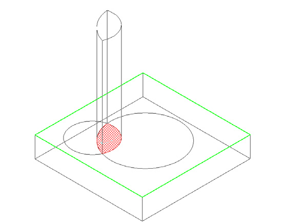
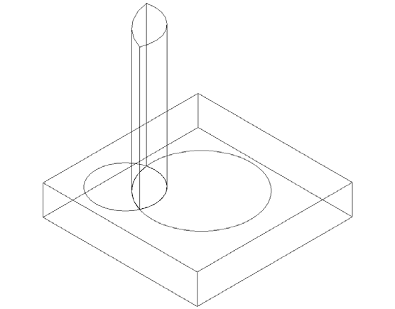
- Select the face of a 3D object.

- Select the 3D object to be the target of the extrusion.

- The result is a new 3D object.

...
- Hold down the SHIFT key to select multiple faces.

- Release the SHIFT key and select the target object.

- You will have a multiple extension.

There are some limitations that must be respected to create valid results:
Resulting extrusions must intersect the target body when extended, or the operation will be invalid.
You cannot extrude adjacent faces.
Adjacent faces are extended along with the extrusion face. Adjacent curved faces and adjacent slanted faces will continue their curve or slant when the selected face it extruded


You can extend to ACIS surfaces, but only if the target body completely intersects the resulting extrusion.


You cannot extrude a face to the same 3D object that the extrusion face belongs to.
When extruding to a ACIS surface you can remove the remnant "excess" of the target surface using the Facet Edit tool.
- Select the facet.

- Press the DELETE key.

| Anchor | ||||
|---|---|---|---|---|
|
| Anchor | ||||
|---|---|---|---|---|
|
...
- Select the profile you want to project, then select a point on the path where you want the projection.

- Click more points where you want profile projections.

If you rotate the model, you can see the profiles in 3D.

- Select Finish from the local menu or Inspector Bar to exit the function.
Local menu options:
Make Copy Profile: Use this profile to make multiple copies along the path. When unselected, you can Finish or select another profile.

One Step Back: Removes profiles in the reverse order in which they were created on the path.

Unselect Profile: Unselects the current profile, enabling you to select another one.

| Anchor | ||||
|---|---|---|---|---|
|
...
- Select the profile or object you want to project, then select a point on the path where you want the projection.
- Click more points where you want profile projections.
If you rotate the model, you can see the profiles in 3D.
- Select Finish from the local menu or Inspector Bar to exit the function.
...