Available in TurboCAD Pro and Platinum only
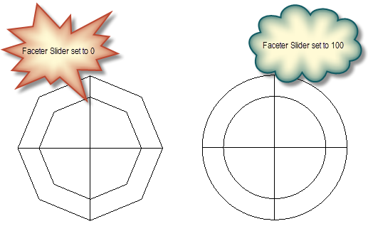
Controls faceting of ACIS 3D solid (not surface) objects, thereby the accuracy of the model representation. Faceting generates polygonal representations of object faces, while maintaining the edge consistency between adjacent faces.
...
Allow Axis Scale: ACIS solid objects can be scaled by entering different scale values in the Inspector Bar for each axis. If not checked, scaling will be uniform, and this uniform values must be entered in the scale fields for at least two axes.
...
Note: This parameter is only relevant for ACIS solids. Use the Selection Info palette if you are unsure about an object's type. For example, if you create a solid box, you will need to explode it once to make it an ACIS solid.
...
Show Selected Axes for Solid Objects: Applies to objects that will be assembled by axis. See Assemble by Axis.
Faceter
...
Draft: The default mode. Default settings cannot be changed.
Quality: Provides better quality than Draft, but the default settings cannot be changed.
Custom: Enables you to control default tolerance parameters.
Custom Faceter Parameters: If Custom is the faceter mode, you can set the following parameters:
Surface Tolerance: The maximum distance between the facet and the part of the solid it is representing, thereby setting how closely the facets represent the surface.
Normal Tolerance: The maximum angle between two adjacent nodes of a facet (actually the normal deviation), thereby setting how accurately the facets represent the solid, and the rendering quality. This control is usually independent of model size.
Maximum Edge Length: The maximum facet edge length. As the length decreases, the number of facets increases. This is the way to subdivide facets into more planar facesm.The level of facet refinement which is used to display ACIS objects can be set by the Faceter Quality slider.
For greater customized control, select the Expert Faceter Parameters option, and then specify the desired values.
Expert Faceter Parameters
Normal Tolerance: Specifies the maximum angle (in degrees) between surface normals at points on a facet. The default normal_tolerance value is 0, which means the normal tolerance is ignored.
Surface Tolerance: Specifies the maximum allowed distance between the surface and the mesh. The default surface_tolerance value is -1, which means the surface tolerance is ignored.
Max Edge Length: Constrains the maximum length of a side of a grid cell in object space. More precisely, the maximum edge length value constrains the maximum length of a diagonal of a grid cell, because the length of a grid cell diagonal provides an upper limit for the edge length of a facet. Therefore, this parameter also constrains the maximum edge length of a facet. The default max_edge_length value is 0, which means the maximum edge length is ignored.
Min Grid Lines U: Specifies the minimum number of u grid lines (i.e., grid lines in the u-direction). The default min_grid_lines_u value is 0.
Min Grid Lines V: Specifies the minimum number of v grid lines (i.e., grid lines in the v-direction). The default min_grid_lines_v value is 0.
Grid aspect ratio-Specifies the maximum ratio of the long side to the short side of a grid cell in 3D space. The aspect ratio value does not guarantee that triangles will have a particular aspect ratio; it applies only to the aspect ratio of grid cells. If the value of the grid aspect ratio parameter is less than or equal to 0.0, the grid aspect ratio is ignored. If the value of the grid aspect ratio parameter is greater than 0.0 and less than or equal to 1.0, a value of 1.0 is used. The default grid_aspect_ratio value is 0, which means the grid aspect ratio is ignored.
Use Grid to Edges: Specifies whether a grid is used and whether the points where the grid cuts the edge is inserted to the edge. The default value is FALSE.
Object Specific Faceting
Faceting can be controlled on an individual object basis via the Properties of the object. Object specified faceting overrides the global setting in the ACIS settings.

Two entities with new faceter options: