Changing the Workplane
While working in 3D, you will probably have to change the workplane frequently to create objects that have the correct location and orientation.
For example, create a cube based on the default workplane. If you want to create a cylinder on the top face of the cube, you must move the workplane up to this face. Then you can place the cylinder in the correct location.

The workplane can also change when you select objects, depending on whether the 2D or 3D Selector is used. See See 2D-3D Selector.
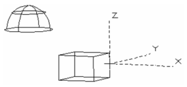
Workplane by View
![]()
Sets the workplane according to the current view.
...
- Click By Entity, and the cursor becomes a dashed representation of the current UCS. Click the desired object.
 The workplane is placed along the plane on which the object was created.
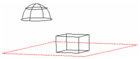
- To change the workplane to another object, use the tool again. Click the desired object.
 The workplane is positioned according to the selected object.
 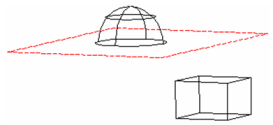 ----
----
Tip: If an object is listed in the Graphics section of the Design Director, you can set the view to an object's Workplane by Entity, and set this workplane as the current workplane. See See Design Director-Graphics.----
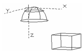
Workplane by 3 Points
![]()
Sets the workplane to fit three points. You can select these points, or enter their coordinates in the Coordinate Fields.
...
Note: The workplane is set to a facet automatically by default, as long as Workplane by Face mode is checked in the Drawing Aids window. You can open this window by right-clicking on the SNAP or GEO field at the bottom of the screen. See See Snap Settings.
...
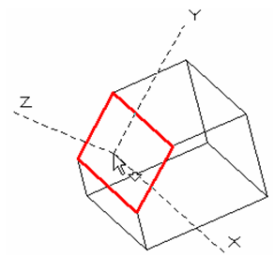
- Move the cursor to the desired facet, which is highlighted in red, and the workplane axes are displayed.
 ----
----
...