Available in TurboCAD Pro and Platinum only

Modifies a facet of a solid (not surface) object by imprinting a closed 2D profile object (polyline, polygon, circle, arc, or curve). Multiple profiles can be imprinted at once. You can also add a fillet to the bottom and/or chamfer to the top.
Imprint uses uses Boolean operations of of Add and and Subtract on on the original solid and the extrusion of the 2D closed profile. See See 3D Boolean Operations.Note: The .
Imprint is available on the fly-out toolbar from the Drawing Tools toolbar or the 3D Object toolbar.
| Note |
|---|
NOTE: The closed 2D profile object must be located on a facet of the 3D object. You can use text as part of the compound profile for imprinting. |
Imprint
...
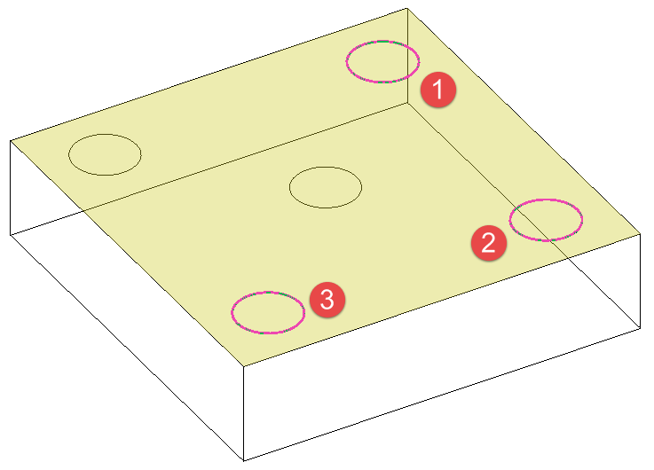
Auto Detect
Adds or subtracts the extrusion of the closed profile to/from the solid, depending on which direction the profile is extruded.
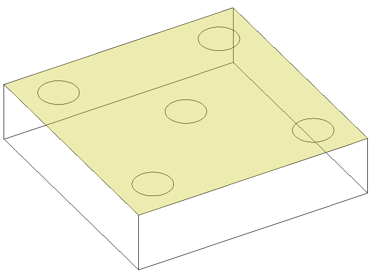
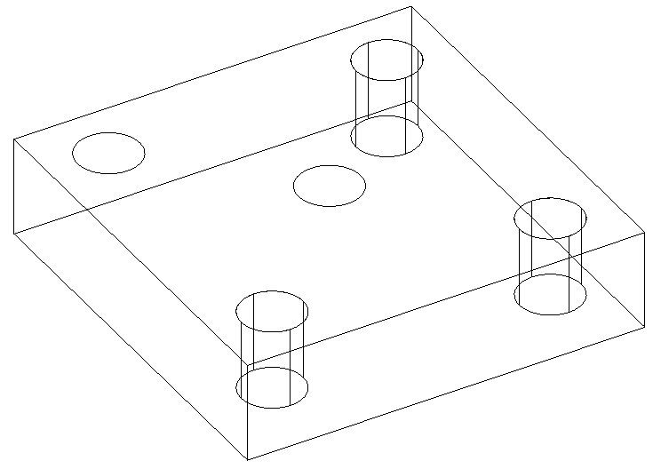
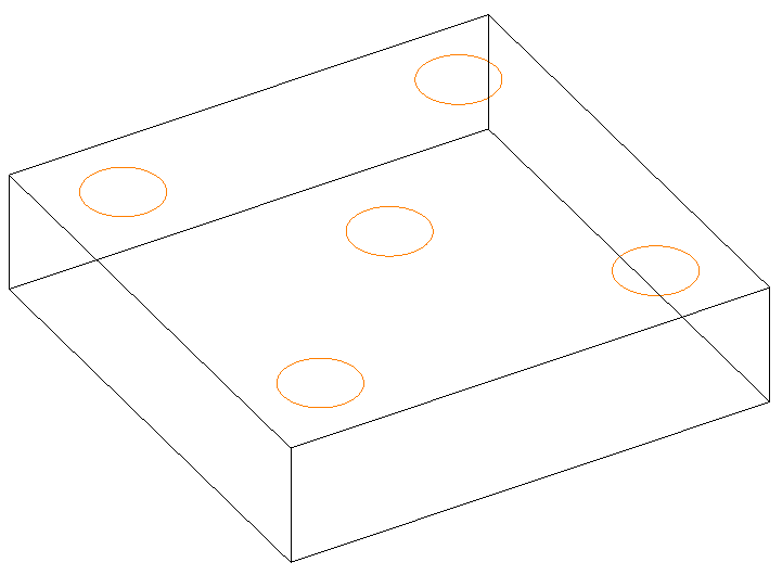
- Start with a solid object with one or more profiles on one facet. ActivateImprint and select the facet that will be imprinted.
- Make sure Auto Detect is selected. In this example, the last two options in the Inspector Bar have no blend (fillet or chamfer).
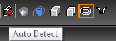
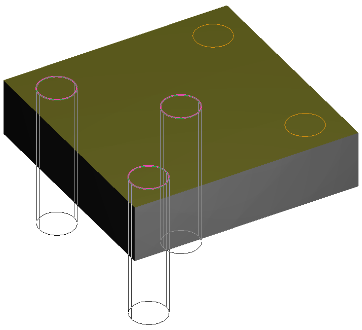
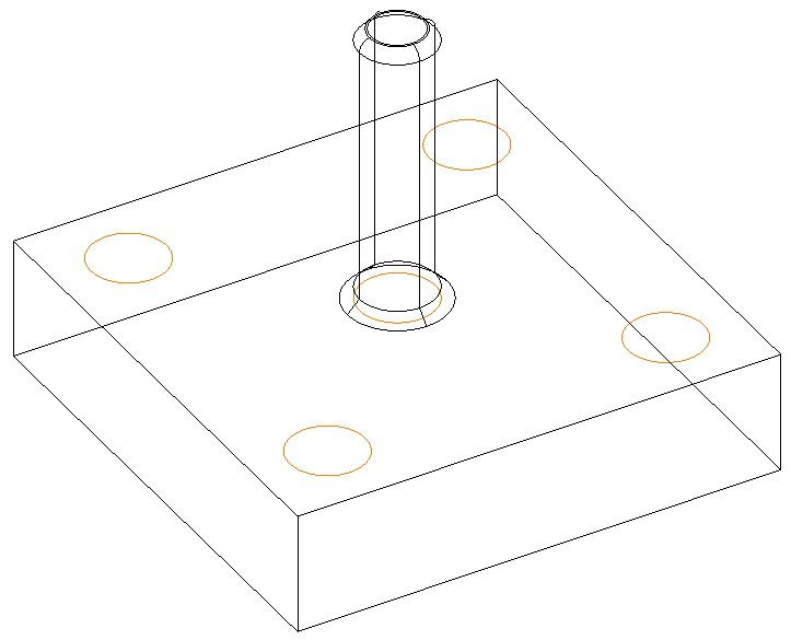
- Select the closed profile. If you want to select more than one profile, press the Shift key.
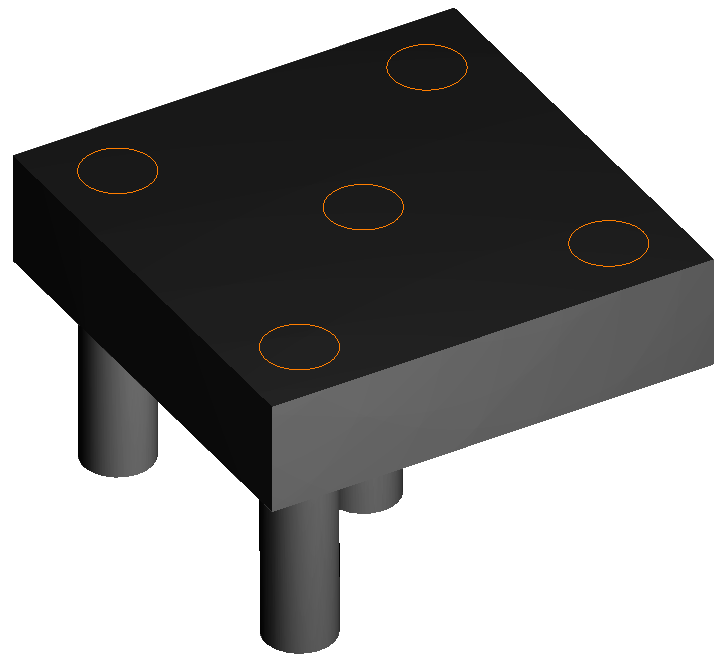
- Pull the profiles away from the solid, and click to create the imprint, or enter a Height in the Inspector Bar. Because the extrusion direction was outward, the extrusions were added to the solid.
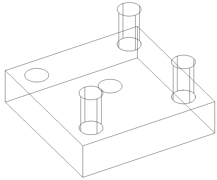
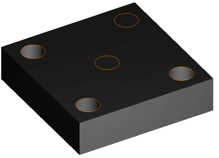
- If you Undo and recreate the imprint, pushing into the solid this time, the extrusions will be subtracted from the solid.
Imprint Add
Adds the extrusion of the closed profile to the solid, regardless of the extrusion direction.
- Select the desired face.
- Now select Add.

- Select and extrude the profile, and now the extrusion is added to the solid.
Imprint Subtract
Adds the extrusion of the closed profile to the solid, regardless of the extrusion direction.
- Select the desired face.
- Now select Add.
- Select and extrude the profile, and now the extrusion is added to the solid.
Imprint with Chamfer or Fillet
You can add a chamfer or fillet to the top or bottom of the imprint.
- Start with a solid object with one or more profiles on one facet. Activate Imprint and select the facet that will be imprinted.
- In this example, Auto Detect is selected. When the last two options are set to Normal Top and Normal bottom, the imprint edges will be sharp.

- To fillet or chamfer, click the option icons to set them to Fillet Top / Bottom or Chamfer Top / Bottom. Clicking repeatedly will scroll through the options. In this example, the bottom has a chamfer, and the top has a fillet.

- Set the Top radius and Bottom radius.

- Select and extrude the profile. The top is filleted and the bottom is chamfered.
- You can edit all parameters of the imprint (including changing or removing fillets and chamfers) in the Selection Info palette.

Imprint with Dimple Sheet Metal
You can use the imprint tool to create a dimple effect as in sheet metal.
- Start with a solid object with one or more profiles on one facet. Activate Imprint and select the facet that will be imprinted.

- Select the Dimple sheet metal option.

- Select a closed profile.

The height must be a negative value greater than the sheet thickness. The top radius must be equal to or greater than the thickness of the sheet.


Imprint with Dimple Sheet Metal
You can use the imprint tool with slots use as the profile/s.
Select the desired face.
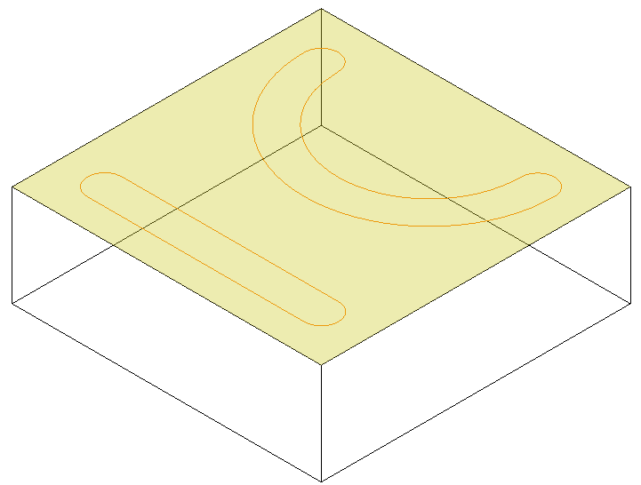
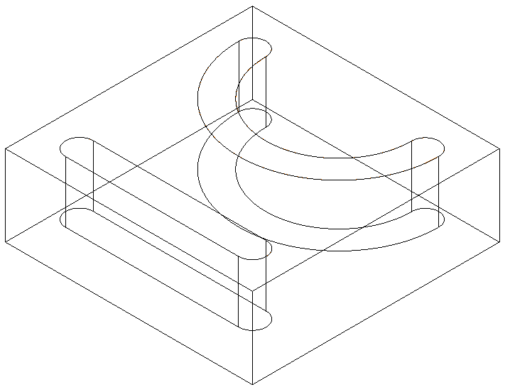
- Now select Slot operation.

- Select and extrude the slot profile/s, and now the extrusion is combined to the solid.

Editing Imprint Parameters
The Selection Info palette can be used to edit parameters of the imprint itself, as well as the fillets and/or chamfers.
Select the imprint, and its Part Tree appears at the top of the palette. UnderImprint, highlight Simple Extrude.

At the bottom of the palette, the Simple Extrude category contains parameters for the imprint body:
- Draft Angle: Creates an extrusion of increasing or decreasing cross-section. Enter the angle of deviation from the extrusion path.
- Draft Start / End Distance: If Draft Angle = 0, you can specify a draft angle by entering the offset distances.
- Height: The distance of the extrusion.
- Direction: Switch between one-sided and two-sided.
The Imprint category is where you can change the imprint type (Auto Detect, Add, or Subtract) and change or remove fillets and chamfers and change their radii.