...
- This example started with a Simple Extrude, based on a linear polyline. Make sure that the Use compound profile option is turned on, otherwise the profile will not be linked to the resulting extrusion.
- Highlight Polyline and change its color and line weight.
Now the polyline is easily differentiated from the solid.
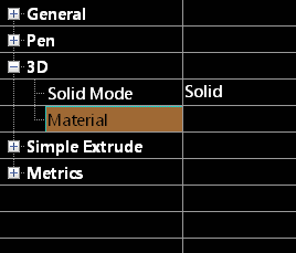
For the Simple Extrude, you can edit all parameters that are available in its Properties window. For example, the 3D category has an option to change the object into a surface object (uncheck Solid Mode), and object and to set the object's Material. - Under Simple Extrude, increase the Height and add a slight Draft In (out) Angle.
The solid is now higher with drafted walls. - Use Fillet Edges to round one edge (see Fillet Edges.) Then use Shell Solid to shell this shape, leaving the top face open (see Shelling Solids.)
In Selection Info, the Extrude, Fillet and Shell operations are listed under "Part Tree." - The Simple Extrude is based on the polyline, and changing the polyline will update the solid. Highlight Polyline and click Select.
- Scale the polyline in Select Edit mode to make it longer. The solid shape, as well as the fillet and shelling update automatically.
- Subsequent operations do not have to update automatically. To disable this, right-click on "Shell" and select.
Note: If you click Suppress Operation, the operation will be removed from part history, though its item will still remain in the list. You can bring the operation back into the model by selecting Unsuppress Operation. - To edit the fillet, highlight it and select.
- Edit in Place enables you to return to the original operation and make changes. Click another edge for filleting. You could also change parameters such as the fillet radius.
- Select Finish to update the operation. The shell has not updated.
- To update the shell, right-click t and select.
Now the shell reflects the new filleted edge. - For the next operation, create a cylinder, with its workplane located on one of the vertical faces.
- Then use the Boolean operation 3D Subtract to remove the cylinder from the shelled solid. (See 3D Subtract.)
- The 3D Subtract operation is now listed. If you expand it, you can see the Cylinder on which it is based. Highlight the cylinder, and click Select.
- Move the cylinder, which in turn updates the 3D Subtract operation.
- For another way to edit the cylinder, select Edit Content.
- The cylinder is now the only object in the drawing area, and any changes will modify the operations currently based on the cylinder. Make a copy of the cylinder so that they overlap.
- Then use 3D Subtract to get this shape:
- When finished, click Finish Editing Content.
The entire solid is updated, based on the modified cylinder. - For one of the solid operations, open Metrics. It only informs you that the object is a solid, as opposed to a surface.
- Click Show Physical Metrics.
This displays properties such as volume, area, center of gravity, and moments of inertia.
...


