...
Menü: Ändern, 3D-Objekt, Biegen, Entlang Pfad biegen

This tool bends a ACIS solid to conform to a 2D path created from a polyline, arc, or curve. The 2D entity must not be closed.
To use the Brnd to Path tool:
- Select the Bend to Path tool.
- Select the solid to be bent.

- Specify the Inside/Outside axis by selecting a first point and then a second point. This axis defines the line along the object that will be bent around the path.

- Specify the initial direction of bending by selecting a point or by entering an angle value in to the Inspector bar. The direction is indicated by a blue arrow. This point and the initial point of the inside/outside axis combine to create a bend axis which defines the orientation of the object as it is bent around the path. After creation this value can be changed via the Propeties in the selection info palette if the Part Tree is turned on (Highly Recommended).

- Select the path to that the object will be bent around.

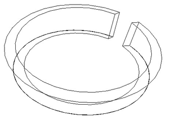
The result:

If the inside/outside axis had been diagonal...

This would have been the result:

If the inside/outside axis had be drawn along the base...

This would have been the result:

If the bend axis had been define diagonally...

This would have been the result:

Options:
- Leave source copy: When this option is selected a copy of the original object will be left in the model. It can be toggled via the Local menu or the Inspector bar.
Demo VideoDieses Werkzeug biegt ein ACIS-Volumenkörperobjekt entlang eines aus einer Polylinie, einem Bogen oder einer Kurve erstellten 2D-Pfads. Das 2D-Element darf nicht geschlossen sein.
So verwenden Sie das Werkzeug Entlang Pfad biegen:
- Wählen Sie das Werkzeug Entlang Pfad biegen aus (Menü: Ändern, 3D-Objekt, Biegen, Entlang Pfad biegen).
- Wählen Sie den zu biegenden Volumenkörper aus.

- Definieren Sie die die innere/äußere Achse, indem Sie einen ersten und zweiten Punkt auswählen. Diese Achse definiert die Linie entlang des Objekts, das entlang des Pfads gebogen wird.

- Definieren Sie die Ausgangsrichtung der Biegung, indem Sie einen Punkt auswählen oder durch Eingabe eines Winkelwerts in die Kontrollleiste. Die Richtung wird durch einen blauen Pfeil angezeigt. Dieser Punkt und der Ausgangspunkt der inneren/äußeren Achse werden miteinander kombiniert, um eine Biegeachse zu erzeugen, die die Richtung des Objekts beim Biegen entlang des Pfads definiert. Dieser Wert lässt sich bei aktivierter Teilestruktur (empfohlen) über die Eigenschaften in der Palette Auswahlinformationen ändern.

- Wählen Sie den Pfad entlang dessen das Objekt gebogen werden soll.

Ergebnis:

Wenn die innere/äußere Achse diagonal gewesen wäre...

... hätte das Ergebnis so ausgesehen:

Wenn die innere/äußere Achse entlang der Basis gezeichnet worden wäre...

... hätte das Ergebnis so ausgesehen:

Wenn die Biegeachse diagonal definiert worden wäre...

... hätte das Ergebnis so ausgesehen:
Kontextmenüoptionen:
Quellgrafik beibehalten: Wenn diese Option ausgewählt ist, wird eine Kopie des Originalobjekts im Modell belassen. Die Option lässt sich über das Kontextmenü oder über die Kontrollleiste aktivieren/deaktivieren.
Demo-Video (englisch):
| View file | ||||
|---|---|---|---|---|
|
...