Tracing
- Brian Carter (Unlicensed)
Available in TurboCAD Pro and Platinum only_
The Trace tools originate from the stand-alone ScanPro application, which has now been incorporated into TurboCAD Pro. They enable you to create 2D raster-to-vector tracings of inserted pictures (see Inserting a Picture) or of geometric objects.
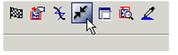
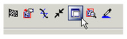
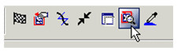
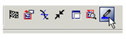
Trace tools are available on the Tools toolbar, which you can display by right-clicking in any toolbar area and selecting Tools.
Before creating a tracing, it's important to understand the local menu options, since these greatly affect the appearance and quality of the trace.
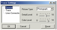
Trace Options: Settings for trace quality.
![]()
The General page provides options for the Picture Type. The Detail Level and Color Level values update with the picture type.
The Trace page controls the quality of the tracing.
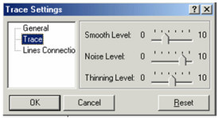
Smo oth Level: Reduces jags and discontinuities in lines and curves.
No ise Level: Reduces spots.
Th inning Level: Reduces line widths.
The Li nes Connection page contains parameters relevant when Connect Lines is activated.
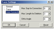
Max Gap for Connection: The largest gap which will be closed when connecting lines.
Max Length for Deletion: The largest segment that can be deleted, i.e., breaking the lines on either side.
Ortho Angle: The angle at which line segments will be joined into polylines.
Cu rve Recognition: Traced polylines will be created as curves. Otherwise they will be created as lines and polylines.
![]()
*Conn .
Gr ab the Window: If on, then the tracing is made directly behind the traced objects. If off, the tracing is saved to the buffer.
The advantage to grabbing the window is speed, but some artifacts may be left on the image (grid, flyout controls, etc.). When not used, there are no artifacts, and the image size is limited only by system memory. However, the tracing takes longer, especially in render mode.
Preview Mode: A trace preview will appear in magenta over the image.
Tracing Colors: By default, all colors will be used for tracing. This option is used when you want to trace around only selected colors.
The following two options are relevant only for Trace by Point:
Show / Hide Trace Rectangle: Toggles the display of the tracing rectangle, defined by its aperture size.
Nearest Graphic Only: Traces only the object closest to the tracing rectangle's center, identified by crosshairs.
For any documentation issues please email:
Documentation@imsidesign.com