You can find any tool by the Menu Structure HERE: https://turbocaddoc.atlassian.net/wiki/display/TC21UG/Menu+Structure
You can find the menu location of any tool by name HERE: https://turbocaddoc.atlassian.net/wiki/display/TC21UG/Tools+Mapped+to+Menus
2D - 3D Selector
- Brian Carter (Unlicensed)
Usage of the 2D Selector can be set in the Selector Properties window. This can be opened by right-clicking anywhere while in Select mode, and selecting Selector 2D Properties from the local menu. (If the 3D Selector is active, the local menu item will be Selector 3D Properties.)
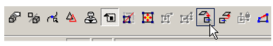
You can also click the icon on the Inspector Bar to open the Selector Properties.
![]()
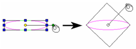
While working, you can easily switch between 2D and 3D Selector Mode, without having to open the Selector Properties window.
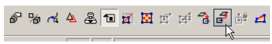
Simply click the Toggle 2D/3D* icon on the Inspector Bar.
![]()
General
Controls how 2D and 3D objects are selected, and what transformation fields appear in the Inspector Bar.
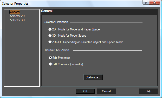
2D Mode for Model and Paper Space: Treats all objects as if they are 2D, and only uses the 2D selection rectangle. The Inspector Bar contains transformation fields in X and Y only.
3D Mode for Model Space: Treats all objects as if they are 3D, and only uses the 3D selection box. The Inspector Bar contains transformation fields in X, Y, and Z.
2D/3D Depending on Selected Object and Space Mode: Treats objects differently; 2D objects are treated as 2D objects and 3D objects are treated as 3D objects.
Edit Properties: If this option is set double clicking on any object with the selector will open it Properties dialog.
Edit Content (Geometry): If this option is set double clicking on any object with the selector will set the object for editing. For most objects the will be the equivalent of activating the edit tool. For text double clicking will allow you to edit the text content.
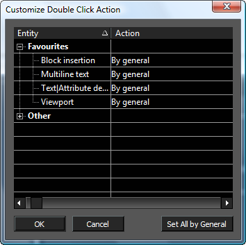
Customize: Allows you to specify how double clicking will act for each class of objects.
Selector 2D
Options for 2D selection and fields in the Inspector Bar.
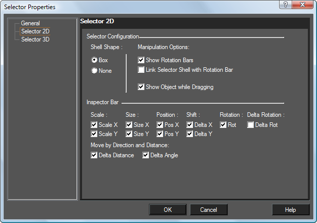
Shell Shape: Select None to make the selector shell (bounding rectangle) invisible.
Manipulation Options
Show Rotation Bars: If unchecked, the rotation bar is not shown and is not accessible.
Link Selector Shell with Rotation Bar: If checked, when you press Ctrl and move the rotation handle, the selector shape will change accordingly.
Link Selector Shell not checked
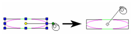
Link Selector Shell checked
Show Object while Dragging: Displays the selected objects dynamically as they are transformed. If not checked, only the selection shell is visible.
Inspector Bar: Controls the 2D transformation fields that appear on the Inspector Bar. See Inspector Bar.
Note: The 2D Selector always moves the UCS (workplane) to the selection.
Selector 3D
Options for 3D selection, containing additional options for selection boxes and Inspector Bar fields. Many of these parameters are the same as for the Selector 2D page.
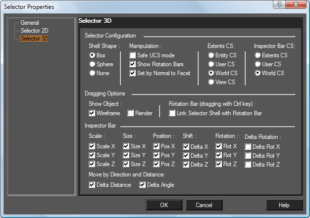
Shell Shape: Box is the default. The Sphere shell is useful for visualizing rotation, but does not allow drag and drop scaling. Select None to make the selector shell invisible.
Manipulation: Options for manipulating the display.
CS Stands for COORDINATE SYSTEM
Safe UCS Mode: Prevents changes to the current workplane when you manipulate objects with the 3D Selector. If unchecked, you will get a warning message when using 3D Selector for 2D object replacement.
Warning: Use this option with caution. Simply moving an object along the same workplane will not change the workplane, but rotating an object will change the workplane.
Extents CS: Sets the coordinate system (workplane) used by the selector shell. Because these settings work in tandem with other settings, their performance can become complex. Careful study of the Extents CS and Coordinate system parameters will help you understand this powerful tool.
- Entity CS: Selector shell CS equals the CS of the selected objects.
- User CS: Selector shell CS equals the CS of the current workplane.
- World CS: Selector shell CS equals the world CS.
- View CS: Selector shell CS equals the CS of the plane of the current view.
Inspector Bar: Sets the coordinate system (workplane) used by the Inspector bar. Because these settings work in tandem with other settings, their performance can become complex.
- Entity CS: Inspector bar CS equals the CS of the selected objects.
- User CS: Inspector bar CS equals the CS of the current workplane (UCS).
- World CS: Inspector bar CS equals the world CS.
Inspector Bar: Sets the fields that appear in the Inspector Bar (see Inspector Bar.)
Scale and Size: X, Y, and Z fields.
Position: Current location.
Shift: Change in position.
Rotation: Rotation from position relative to the Extents CS.
Delta Rotation: Change in rotation from the current position.
Move by direction and Distance: Delta Distance and Delta Angle work in conjunction.
Delta Distance: the distance an objects is moved along the specified Delta Angle
Delta Angle: the angle along which an objects is moved the specified Delta Distance
There are only four possible scenarios where the user changes the value in either one or both of these fields, and then presses Enter. This is similar, in some ways, to drawing a line segment by length and angle.
Like the other Delta fields, once the user presses Enter and the changes have been made the fields will revert to a value of 0 (zero).
The Use Cases are as follows:
#1
Delta Angle Field Changed, Delta Distance Field Changed
Result
Everything that is selected moves the specified Distance at the specified Angle. Example: Delta Distance (16mm) at 36.8 degrees. The selected object/s will move 16mm at 36.8 degrees.
#2
Delta Angle Field Unchanged Delta Distance Field Changed
Result
Everything that is selected moves the specified Distance at 0 degrees. Example: Delta Distance (16mm) at 0 degrees. The selected object/s will move 16mm at 0 degrees.
#3
Delta Angle Field Changed Delta Distance Field Unchanged
Result
Nothing happens. Moving a zero distance is a Null.
#4
Delta Angle Field Unchanged Delta Distance Field Unchanged
Result
Nothing happens. Moving a zero distance is at a zero angle is a Null.
Coordinate System: Sets the CS references in the Position in Space fields.
When using the 3D Selector, the local menu and Inspector Bar provide three options that do not appear when working in 2D.
Set UCS by Selector: Moves the UCS origin to the selection reference point.
Set Selector by UCS: Moves the selection to the UCS origin (similar to the Format / Place on WorkPlane option for 2D objects).
Note: The 2D Selector always moves the UCS (Workplane) to the selection.
Lock/Unlock Axis: Locks or unlocks a rotation bar. Move the cursor to the end of the rotation bar you wish to lock or unlock, and select Lock or Unlock Axis from the local menu.
Auto select compound profile: When selecting curves for a geometry tool, this option will enable you to select smoothly connected chains of curves.