Snap Modes
- Brian Carter (Unlicensed)
This section lists all available snaps and geometric aids. When accessed from the Snap Modes toolbar or from the menu, these are running snaps (permanent until turned off). When accessed by a SEKE or from the local menu, they are one-time snaps.
No Snap
SEKE:* S

When on, turns off all snap modes. With snap modes off, you define points by simply clicking, or by using the Inspector Bar and Coordinate Fields.
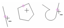
Ve rtex Snap
SEKE:* V

Snaps to the nearest vertex. A vertex can be an endpoint of a line or line segment, corner of a polygon, or endpoint of an arc or curve.

Mid dle Point Snap
SEKE:* M

Snaps to the midpoint of a line or line segment.
Di vide Point Snap

Snaps to one of the division points of an arc or line segment.
The default number of segments is 3, but you can change this in the Segments field of the Drawing Aids window. Open this window by right-clicking on the SNAP or GEO button next to the Coordinate Fields.


Tip: You can also divide arcs and line segments while using the Edit Tool, by selecting Divide Segment or Arc Divide from the local menu. See Edit Tool.
Ce nter Snap
SEKE:* C

Snaps to the center of an arc, circle, or ellipse.

Cent er of Extents Snap
SEKE:* E

Snaps to the center of extents of a 2D or 3D object. This is the center of the bounding rectangle (2D) or box (3D) that encloses the selected object.

N earest on Facet Snap

Snaps to the nearest point on a facet, or to the projection of this point onto the current workplane.
Qu adrant Point Snap
SEKE:* Q

Snaps to the nearest quadrant point (0, 90, 180, and 270 degrees) on a circle, arc, or ellipse.

Inter section Snap
SEKE:* I

Snaps to the intersection of two objects.
Gri d Snap
SEKE:* G

Snaps to the nearest grid point. See Grid.
For details on grid settings, see Grid Options.
If the Advanced Grid option of Frequency is set to a figure greater than one, invisible grid lines will also be detected by this snap mode. See Advanced Grid Options.
Near est on Graphic Snap
SEKE:* N

Snaps to the point on an object closest to the cursor, within the snap aperture.
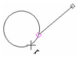
Tan gent Snap

Snaps to a tangent point on an arc, circle, or ellipse, relative to the previous point.
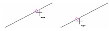
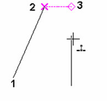
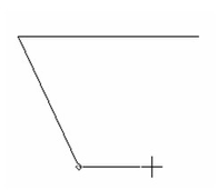
Pro jection Snap

Snaps to a point that is the perpendicular projection image of the last point drawn onto a selected object.
In this example, the line on the right is the projection line. The last point drawn is Point 2, when creating Line 1-2.

Activate the Projection snap and hover over the projection line. Point 3 is the snap point, which is the perpendicular projection of Point 2.

The snap point does not have to lie on the projection line; it can be placed on the extension of the projection line.
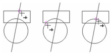
In the case of a circle, the projection point is along the radial from the circle center. If the circle is selected on the left side, the snap point will be on that side.

If you select the circle on its right side, the snap point will be on that side.

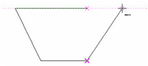
Opposite (Mirro r Point) Snap

Snaps to a point that is the mirror image of the last point drawn, in reference to a selected object.
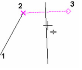
In this example, the line on the right is the mirror line. The last point drawn is Point 2, when creating Line 1-2.
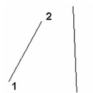
Activate the Opposite snap and hover over the mirror line. Point 3 is the snap point.
In some cases it is important where you select the mirror object. If the circle is selected on the left side, the mirror point will be opposite that side.
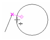
If you select the circle on its right side, the mirror point will be opposite that side.

Or tho Snap
Hotkey:* Shift

When in use, the cursor can only move horizontally or vertically.
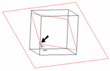
Workplane Intersections Snap

Snaps to intersection curves between 3D objects and the current workplane. (For information on workplanes, see Workplanes)
- The workplane must be displayed (see Displaying the Workplane), and intersection lines must be displayed as well (see Display Intersections with 3D Objects).

- Activate the Workplane Intersections snap along with the snaps you want to use on the intersection lines and curves. In this case Vertex snap is active, and you can snap to an endpoint of the intersection line.
Sh ow Magnetic Point

When in use, a diamond-shaped point will be displayed for the locations of all running snaps. See Magnetic Point.
Ex tended Ortho Snap

Snap to points located orthogonally from existing points. Show Magnetic Point must be turned on.
- Start a polyline with two linear segments, then start the third segment like this:
- To end the third segment, first hover over the start point. This displays an auxiliary line extending vertically from that point. You can snap to points along this line.

- Horizontal auxiliary lines can also extend from this point, when the cursor is to the right or left.
Note: If Always show auxiliary lines is checked in the Drawing Aids window, the auxiliary lines will be displayed, even when you move the cursor away from them.
Appar ent Intersection Snap

Snaps to points where two lines would meet. An auxiliary line is displayed from both lines, extending to this point. Show Magnetic Point must be turned on.
- Start with lines whose extensions will meet (non-parallel). When you pass the cursor over each line, the line's endpoint is marked.

- When the cursor passes over any apparent intersection point, auxiliary lines will be displayed from the actual lines, and their intersection point is marked.


Note: If Always show auxiliary lines is checked in the Drawing Aids window, the auxiliary lines will be displayed, even when you move the cursor away from them.
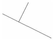
P erpendicular Snap
SEKE: J
Connects a line to another line so that the two lines are perpendicular.
- Select the first endpoint of the line. For the second endpoint, move the cursor over the line to which the new line will be perpendicular.

- Press J.
TC17_UG_04DrawingAidsLayers are virtual levels in a drawing, analogous to acetate tabs (overlays) in traditional drafting. Layers enable you to sort objects in your drawing by type, by creation order, or by any criteria that suits the way you work. You can also use layers to protect certain objects from being edited or deleted.
NOTE: Layers are not related to how objects are stacked in relation to their order of creation. If you change an object's layer, it does not affect its position in the object stack. Setting Up Lay ers
There are two primary ways of creating and editing layers. The Layer manager, and Design Director which is only available in the Pro product. With regard to layers you can do essentially operations with either.
Open the Layer manager by selecting Format / Layers, or by clicking the Layers icon on the toolbar.

This dialog is used to create layers, to assign properties to each layer, and to organize layers. It is divided into two frames. The first frame show the tree containing the layer filter, and layer templates. The second frame show the layers. controlled or derive from the item selected in the tree. The top node of the tree controls and shows all layers in the drawing.

Layer 0 is the default layer, and all objects are placed here unless otherwise specified, or unless another layer is created and made active. Layer $CONSTRUCTION is created when construction geometry is created (see Construction Geometry). Neither of these default layers can be deleted, but you can change their properties.
Layer Set: See Layer Sets.
Columns in Layers window: Use the horizontal scroll bar to see all columns. You can sort the list by clicking on any column heading; the list will be sorted according to the selected parameter.
Visibility (eye icon): Check to make objects on the layer visible.
Re ad-only (lock icon): Check to make the layer read-only, so that objects cannot be edited or deleted. You can add objects to a read-only layer via the Layer drop-down list on the TurboCAD Layers toolbar.
Color: Click on the the color box to open the color dialog, then select a color - The default color is black. Objects will have the layer color if their color is set to By Layer.
Style: Select the line style from the drop-down list and double-click to set it. Objects will have the layer style if their style is set to By Layer.
Or der: Determines the order in which layers are drawn. Order can be used to place certain categories of objects in front of others; objects drawn on higher layers will be "over" those on lower layers. The order numbers are initially set to zero. Layers that have the same order number are sorted alphanumerically. The highest layer number is 32767.
Warning: The Draw Order commands will not function as you expect if objects are on different layers and the layers have different Order values.
Pen Width: Sets the line width. Objects will have the layer width if their width is set to By Layer.
Print Style: Specifies the Print Style to be used by objects on that layer. Print Style Options.
VP Columns in Layers window: In addition to the main columns in the Layers window there are five columns with a VP prefix. VP stands for Viewport, and these columns are use to control how objects will appear within a selected viewport.
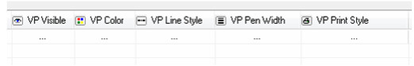
The columns are: VP Visible, VP Color, VP Line Style, Pen Width, Print Style.
The VP columns operate in the same way as the main columns, except the settings effect on selected viewports.
To use the VP column settings: - Open the Layer Manager.
- Go to Paper Space.
- Select the Viewports you wish to configure.
- Apply the settings in the VP columns of the Layer Manager.
NOTE: Remember that settings which control object appearance via the Layer Manager (e.g. VP Color) only affect the properties objects which are set to By Layer.
Layer Manager Toolbar
Refresh: Refresh the Layer manager display.
New Layer Filter: Creates a new Layer filter. Assign a name to the filter then setup the filter in the Layer Filters dialog.
Edit Filter Parameters: Open the layer filter currently selected in the tree in the Layer Filters dialog.
Edit Layer Sets: Opens the Layer Set dialog to create and edit layer sets.
New Layer Template: Creates a new layer template from the currently selected layers.
New Layer: Creates a new layer. The default name will include a prefix by default, but the name can be changed.
Delete Layer: See Snap Modes.
Activate: Sets the currently selected layer (only one) as the active layer. This will effect any currently active drawing tool or currently selected object.
Select By: Selects all objects on the currently selected layers.
Edit Properties: Opens that layer page of the Drawing Options.
Visible/Invisible All: If any layer is invisible all layers are made visible. If all layers are visible they are all made invisible.
Invert Visibility: Turns all visible layers invisible, and all invisible layers visible.
Exclusive Visible: Makes only the currently selected layers visible, all other become visible.
Lock/Unlock All: If any layer is unlocked all layers are locked. If all layers are locked they are all unlocked.
Invert Lock:
Exclusive Lock: Makes only the currently selected layers locked, all other become unlocked.
Layer Prefix: By default, the layers are named "Layer 1, Layer 2," etc. You can change or remove the prefix. The @ symbol is a placeholder for the automatic layer number.
Note: Many of the functions available from the Layer toolbar are also available by right clicking and opening the local menu.
Cr eating a New Layer
- , then assign a name for the layer in the Layer column (or accept the default name).
- Adjust the various layer settings, such as color and line style.
Del eting a Layer
You may delete any layer except Layers 0 and $CONSTRUCTION. Layers can be deleted even if they contain objects.
If the layer to be deleted is set as the default for a tool (in the General page of a tool's Properties window), you will receive a warning message before the layer is deleted.
- Select Layers, and select the layer to be deleted.
- Click Delete Layer. If the layer contains objects, the objects will be deleted. This action can be undone, in case you delete objects inadvertently.
In some cases, objects on deleted layers will be moved to Layer 0, rather than be deleted. If an object exists on Layer 1 in both Paper Space and Model Space, and Layer 1 is deleted from Model Space, in Paper Space the object will be moved to Layer 0. This is due to different Undo buffers for Model and Paper Spaces.
Layer Templates
Layer templates allow you to create and save alternate configurations for layers. Layer templates store how layers are setup, but do not store layers thenselves. Layer templates are saved in a *.lrs file which can be stored anywher in you system directory.