/
Inserting Standard Views
Inserting Standard Views
- Brian Carter (Unlicensed)
Owned by Brian Carter (Unlicensed)
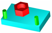
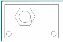
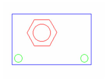
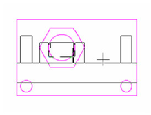
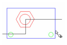
This example will use the following solid model, consisting of a box, 2 cylinders, and a polygonal (hexagonal) prism with a subtracted cylinder.
Note: You can use the Smart Dimension tool
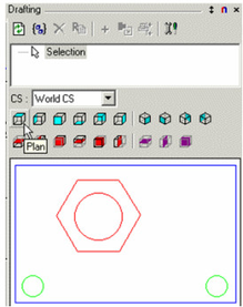
- First, select the objects you want to include in the view. In this case, select all the objects.
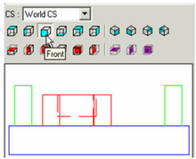
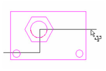
- In the Drafting Palette, select the standard view from the lower group of icons. Start with a Plan view - the preview appears in the palette window.
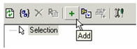
- Add this view to the view list by clicking the Add icon.
The view name appears on the list. You can change it by clicking the Rename icon.
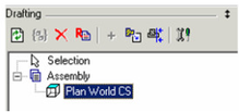
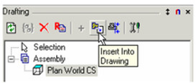
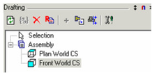
Note: You could have created an assembly of the entire model (see Parts and Assemblies), but selecting objects, then creating and adding a standard view creates an assembly automatically. Note that the Plan view appears under the Assembly header. - Switch to Paper Space. (You can insert views into Model Space as well, but Paper Space is more appropriate.)
- Highlight the view name, and click Insert into Drawing.
- Place the view into the Paper Space. In this case, the scale is too large.
- Press Tab to access the Scale field, and enter the new scale value.
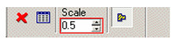
The view is now half as large.
Note: You can also change a view's scale in the Format page of its Properties. - For the next view, create a Front view.
- Add it to the list.
- Use Insert into Drawing, or simply drag it from the palette (drag either the view's name or drag the preview) into the drawing. Again, the scale is too large.
- To set the scale to that of the Plan view, simply drag the Front view over the Plan view. It assumes the same scale.
- This also aligns the Front view to the Plan view. You can move the Front view up and down, but not left or right. (To break this alignment, but preserve the modified scale, press Shift).
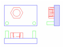
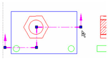
Note: You can always move an aligned view (or any view), by selecting it and dragging its reference point. See Moving Objects in Select Edit. - The available standard views also include section views. Create a *Section .
- When this view is inserted, the scale is too large and the orientation is incorrect, relative to the Plan view.
- Drag the section view over the Plan view. This not only sets the scale, but also sets the orientation.
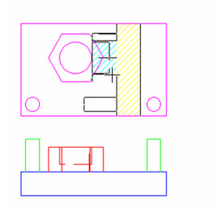
If you press Shift here to break the alignment, the rotation will also change back. Only the modified scale is preserved.
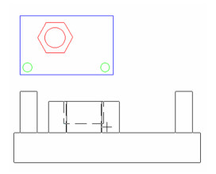
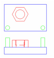
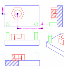
Here are the three views created so far. You can change the hatch pattern of section views in the Section Brush page of the view's Properties.
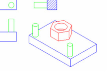
- For the last standard view, create an ISO_SE view.
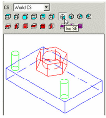
- Insert this view. Because it is isometric, if you try to set the scale by dragging it over one of the other views, the alignment will be diagonal. Therefore, set the scale manually using the Scale field.
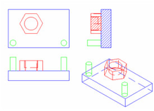
- To change the appearance of any view, double-click it in Select mode to open its Properties. For the isometric view, open the Pen Hidden page. Set the Pattern to Invisible so that hidden lines will not be displayed.
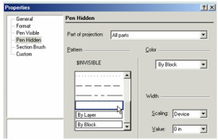
Note: For other Properties options, see Properties of Standard Views.
Here is the modified isometric view.
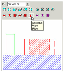
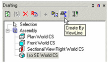
- Finally, the last view will be a sectional view created from one of the existing views. Use a Polyline to draw a multi-segmented section line on the Plan view.
- Click Create by View Line.
- If you want to assign text to the view (such as a letter), enter it in the Text field of the Inspector Bar.
- First select the view whose sectional view you want to create.
- Then select the view line, in this case, the polyline.
- In the next step you define the viewing direction. Move the cursor to switch between the two direction options.
- Click when the direction is correct.
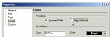
Note: You can also change the viewing direction after the section line is created. Open the section line's Properties to the Format page, and check (or uncheck) Forward Side.
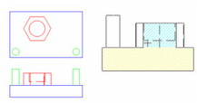
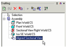
The aligned view is created and is listed in the Drafting Palette, even though it does not yet appear in the drawing.
- Insert the aligned view into the drawing, setting the scale according to the Plan view.
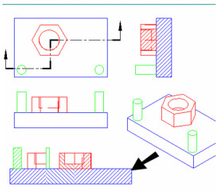
By default, this is an Aligned view - what you see is equivalent to "unfolding" the polyline.
- To switch to a non-aligned view, open the view's Properties to the Format page. Deselect Aligned View.
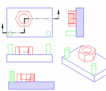
The view is no longer "unfolded."
- For another way to change an aligned section view, use the Edit Tool on the polyline (see Edit Tool).
- Change the polyline by moving, adding, or deleting nodes. The sectional view updates as you change the polyline.
- If you want to add or change characters on the section line, use the General and Text pages of the section line's Properties. See Properties of Section Lines.
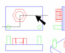
Note that there is a difference between a section and a sectional view. The 3D function Section (see Sectioning Solids) creates an actual section of a 3D object, whereas a sectional view is what you see when looking in the direction of the section line.
In this example, the lower view is a sectional view looking in the direction of Line A-A.
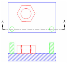
And this is the section taken at Line A-A.
, multiple selections available,
For any documentation issues please email:
Documentation@imsidesign.com