You can find any tool by the Menu Structure HERE: https://turbocaddoc.atlassian.net/wiki/display/TC21UG/Menu+Structure
You can find the menu location of any tool by name HERE: https://turbocaddoc.atlassian.net/wiki/display/TC21UG/Tools+Mapped+to+Menus
Constraining Geometry
- Anonymous
- Brian Carter (Unlicensed)
Available in TurboCAD Pro and Platinum only
Geometric constraints create positional relationships between 2D sketch objects. When used in conjunction with dimensional constraints (see Constraining Dimensions), you can easily control and update objects and dimensions.
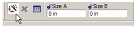
Note: These tools are used for constraining geometry after is has been created. If you want to automatically constrain geometry while it is created, make sure Auto Add Constraints* is active in the Inspector Bar.
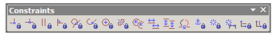
You can display the Constraints toolbar by right-clicking in any toolbar area and selecting Constraints.
Options for constraints can be found in Program Setup; see Constraints.
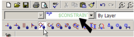
When you activate a constraint, the active layer switches to "CONSTRAINTS." (For details on layers, see Snap Modes.)
In the Inspector Bar, the Illuminate Suitable Entity* option is active by default. This means that only those objects that can be selected for the constraint type will be highlighted when the cursor passes over them. For example, if you are using the Concentric constraint, only arcs, circles, and ellipses will be highlighted and selectable.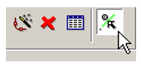
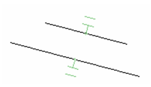
When constraints are created, a constraint marker is attached to the constrained objects. This marker is on the CONSTRAINTS layer, in the layer's color. This example shows two lines that are constrained to be parallel.
Constraint markers can be selected like other objects. To remove a constraint, simply select and delete its marker.
Note: Constraints of selected objects can be viewed in the Selection Info palette. See Selection Info Palette.