/
Constraining Dimensions
This manual serves as the User Guide for all TurboCAD LTE 8 / DoubleCAD 5 Products
Constraining Dimensions
- Brian Carter (Unlicensed)
Owned by Brian Carter (Unlicensed)
Available in TurboCAD LTE Pro / DoubleCAD Pro only
You can use the Calculator Palette to assign constraints to dimensions, making them dependent on other dimensions or values.
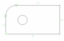
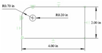
- Start with the same shape used to demonstrate Auto Dimension (see Auto Dimension), and apply Auto Constraints.
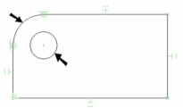
- Add one more constraint: make the fillet and the circle Concentric.
- In the Inspector Bar, make sure Auto Add Constraints is active. With this active, all dimensions you create will be placed as variables in the Calculator Palette. Otherwise, dimensions will be created but they cannot be constrained, or used as constraints for other dimensions. !worddav5e77d38566c61a309135decf6d378dc7.png|height=52,width=74!The dimension types that can be constrained are Orthogonal, Parallel, Distance, Angular, Radius, and Diameter.
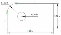
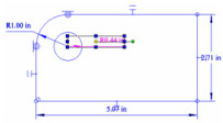
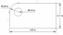
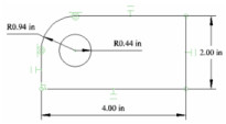
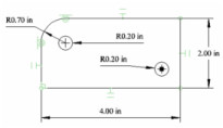
- Apply Auto Dimension, and you should get the following four dimensions:
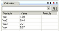
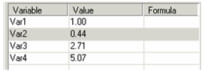
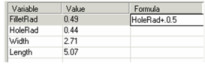
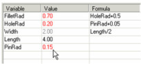
- Make sure the Calculator Palette is open (see Calculator Palette - Variables). The four dimensions you created are listed here, with a variable name assigned to each.
- Select one of the dimensions, and the corresponding item is highlighted in the list.
 ----Note: The dimension's variable can also be seen and edited in the Format page of its Properties.
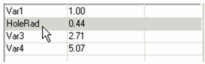
 - Click the variable for the hole radius dimension, and change its name to something meaningful, like "HoleRad." Avoid using spaces in variable names.
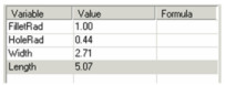
- Change the remaining variable names.
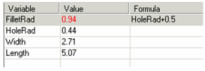
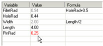
- One way to constrain a dimension is to base it on another dimension. For the fillet radius, click inside the Formula field and enter a formula that makes the fillet radius a set amount (0.5" in this example) larger than the hole radius.
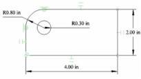
- Press Enter and the fillet radius updates based on the current value of the hole radius. The drawing updates as well.
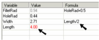
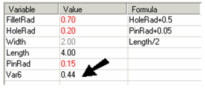
- You can also constrain dimensions to have an exact value, such as the value below for "Length." Width can also be constrained to be a constant factor (such as 1/2) of the length.
- You can also define a new variable independent of any of the current dimensions. "PinRad" is the radius of the pin that fits in the hole, and is assigned a numerical value.
- Once "PinRad" is defined, the hole radius can be made to a set amount larger than the pin.
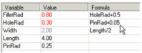
- If "PinRad" is updated, then both "HoleRad" and "FilletRad" are automatically updated.
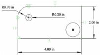
- You can also constrain new dimensions, as long as Auto Add Constraints is active. Create another circle, and inside this circle add a point (see Point). Make the point and the circle Concentric.
 ----Note: The point is added because a circle's center point is not identified as an object; a physical point must be placed there.
 - Add a Radius dimension to the new circle, and its variable appears in the constraint list.
- If you try placing an Equal Radius constraint on the two cir cles, you will receive an error message:
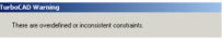
- When you click OK, the problem dimensions are indicated. !worddav149f85e773986bc095e3c64106528738.png|height=115,width=205!This occurs because the second circle is considered to already have a set radius, once it is dimensioned. So constraining it to be equal to the first circle is contradictory. You could have assigned the Equal Radius constraint before assigning the dimension.
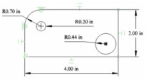
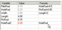
- Undo, and use a dimensional constraint to set the radius, making it equal to "HoleRad."
, multiple selections available,