Creating Standard Views
- Zunair Attif IMSI
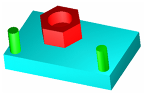
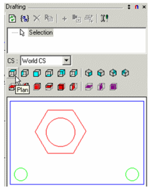
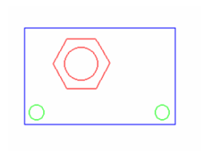
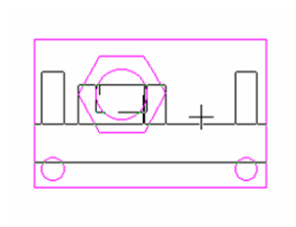
First, select the objects you want to include in the view. In this case, select all the objects. In the Drafting Palette, select the standard view from the lower group of icons. Start with a Plan view - the preview appears in the palette window.
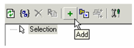
Add this view to the view list by clicking the Add icon.
The view name appears on the list. You can change it by clicking the Rename icon.
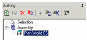
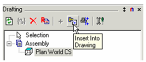
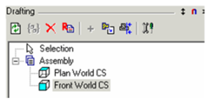
Note: You could have created an assembly of the entire model (see Parts and Assemblies), but selecting objects, then creating and adding a standard view creates an assembly automatically. Note that the Plan view appears under the Assembly header.
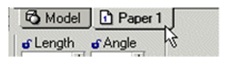
Switch to Paper Space. (You can insert views into Model Space as well, but Paper Space is more appropriate.)
Highlight the view name, and click Insert into Drawing.
Place the view into the Paper Space. In this case, the scale is too large.
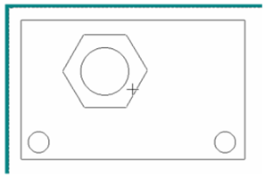
Press Tab to access the Scale field, and enter the new scale value.
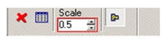
The view is now half as large.
Note: You can also change a view's scale in the Format page of its Properties.
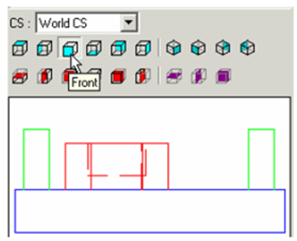
For the next view, create a Front view.
Add it to the list.
Use Insert into Drawing, or simply drag it from the palette (drag either the view's name or drag the preview) into the drawing. Again, the scale is too large.
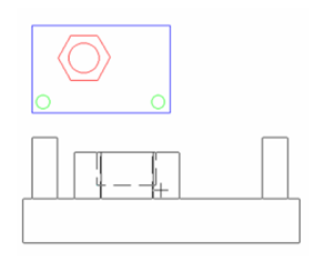
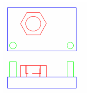
To set the scale to that of the Plan view, simply drag the Front view over the Plan view. It assumes the same scale.
This also aligns the Front view to the Plan view. You can move the Front view up and down, but not left or right. (To break this alignment, but preserve the modified scale, press Shift).
Note: You can always move an aligned view (or any view), by selecting it and dragging its reference point. See Moving Objects in Select Edit